

CUSTOM CAPABILITIES
From Requirement to Tested Assembly
A documented, reproducible process for building custom fiber optic assemblies — engineered, terminated, inspected and packaged to your specification, under one ISO 9001 quality system.
HOW WE BUILD
A four-stage process, documented end to end
Every custom assembly moves through the same controlled workflow — so a prototype built today is reproducible at production volume tomorrow.
-
STEP 01
Requirement Review
Capture application, electrical, mechanical and environmental requirements; agree on fiber, connector and acceptance limits.
-
STEP 02
Fiber & Connector
Select fiber type, connector system, polish (UPC/APC), jacket and cable structure matched to the link budget.
-
STEP 03
Assembly & Termination
Precision cleaving, epoxy polishing and termination under documented process control with traceable materials.
-
STEP 04
Testing & Delivery
100% IL/RL testing, end-face inspection, polarity check, length verification, labeling and protective packaging.

ENGINEERING SCOPE
Customized on every axis that matters
If a parameter affects link performance or service life, we can specify it — and document the build so it is repeatable.
- Connector mix (LC/SC/FC/ST/MPO)
- Fiber type (POF / SMF / MMF / HCS)
- UPC or APC polish
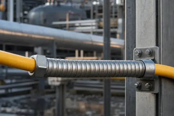
- Jacket: LSZH, PUR, PE, armored
- Custom length & labeling
- Multi-leg / fanout harnesses
- Boot & strain-relief options
- IP67 / outdoor-rated builds
QUALITY CONTROL
Four inspections stand between us and shipment
Optical Performance
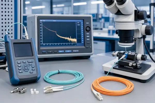
Insertion loss and return loss measured on calibrated sources/meters against your acceptance limits.
End-face Inspection
Connector end-faces inspected under fiber microscopy for scratches, pits, epoxy and contamination.
Polarity & Continuity
End-to-end polarity and continuity verification — essential for MPO/MTP method-A/B/c trunks.
Length & Packaging
Length verification, individual labeling, coil packing and protective shipping containers.
Environmental
Optional thermal cycling, flex and vibration qualification for harsh-environment builds.
Traceability
Lot-traceable materials and a build record kept per assembly for future reproduction.
MATERIALS & STANDARDS
Reference specifications we build to
Indicative ranges — final specification is confirmed against your application and link budget.
| Parameter | Single-Mode (OS2) | Multi-Mode (OM3/OM4) | POF / HCS |
|---|---|---|---|
| Core / Cladding | 9 / 125 μm | 50 / 125 μm | 980 / 1000 μm (POF) · 200/230 (HCS) |
| Insertion Loss (typ.) | ≤ 0.3 dB | ≤ 0.2 dB | ≤ 2.0 dB / 100 m |
| Return Loss | UPC ≥ 50 dB · APC ≥ 60 dB | UPC ≥ 35 dB | application-dependent |
| Connector Polish | UPC / APC | UPC | PC / SMA |
| Jacket Options | LSZH yellow, duplex | Aqua / Magenta / Olive | PUR, PE, IP67 builds |
| Operating Temp. | −40 °C to +85 °C | −20 °C to +70 °C | −40 °C to +85 °C |
| Standards | Telcordia GR-326, IEC 61754 | TIA/EIA, IEC 61754 | IEC 60793, DIN-VDE |
RELATED CASES & INSIGHTS
Field-proven applications & engineering notes

Send us a drawing, BOM or sample
We'll review your requirement and come back with a fiber, connector and process recommendation — typically within one business day.